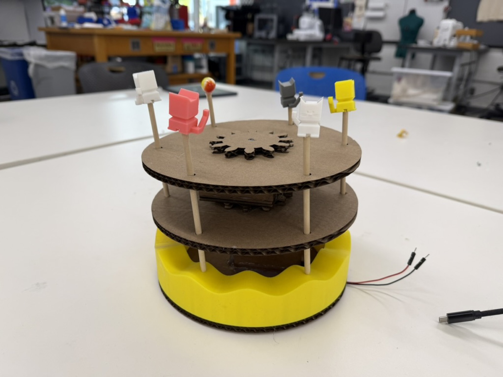
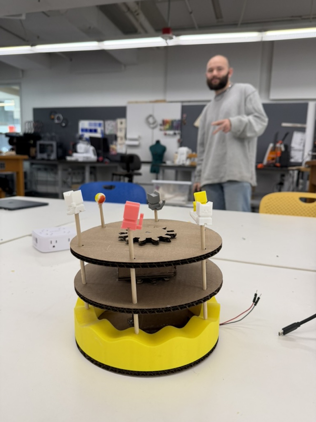
This week's assignment was to build a kinetic sculpture with a motor and power source. I decided to make a merry-go-round where objects move both rotationally and up and down at the same time. Merry-go-rounds were one of my favorite things to ride at the mall as a kid.
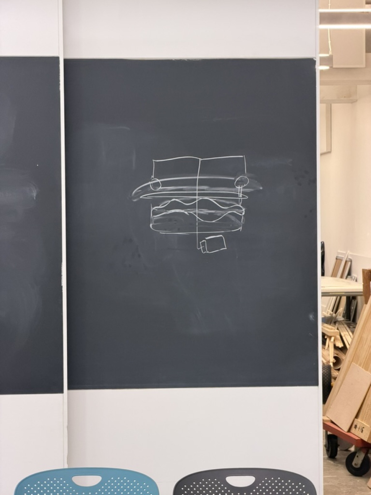
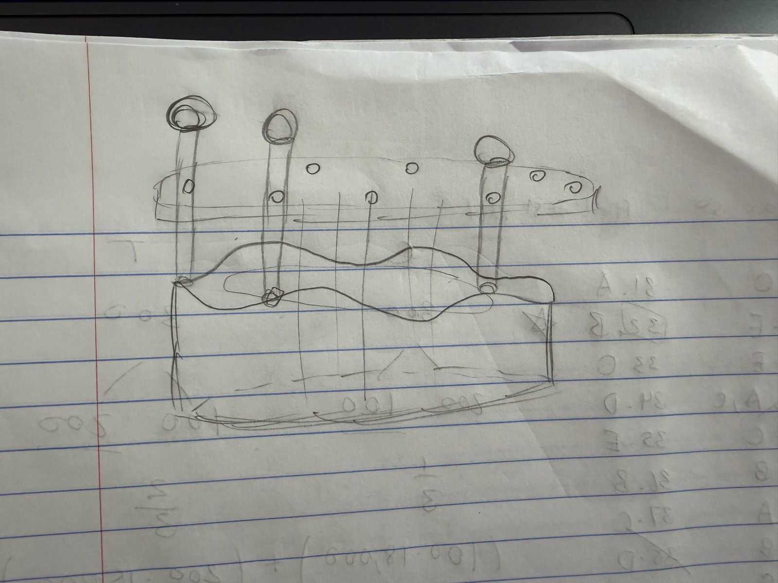
I started by sketching out diagrams on the blackboard and on scratch paper, and consulted Bobby on the best approach. The challenge was that I wanted two motions happening at once (rotation plus vertical movement).
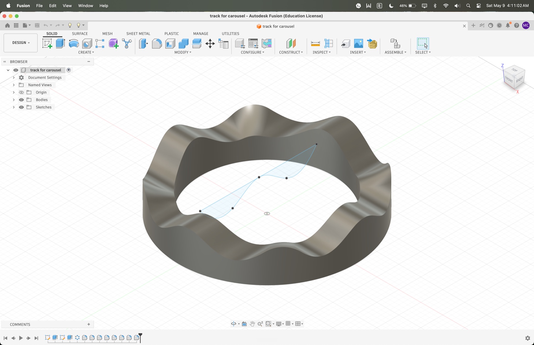
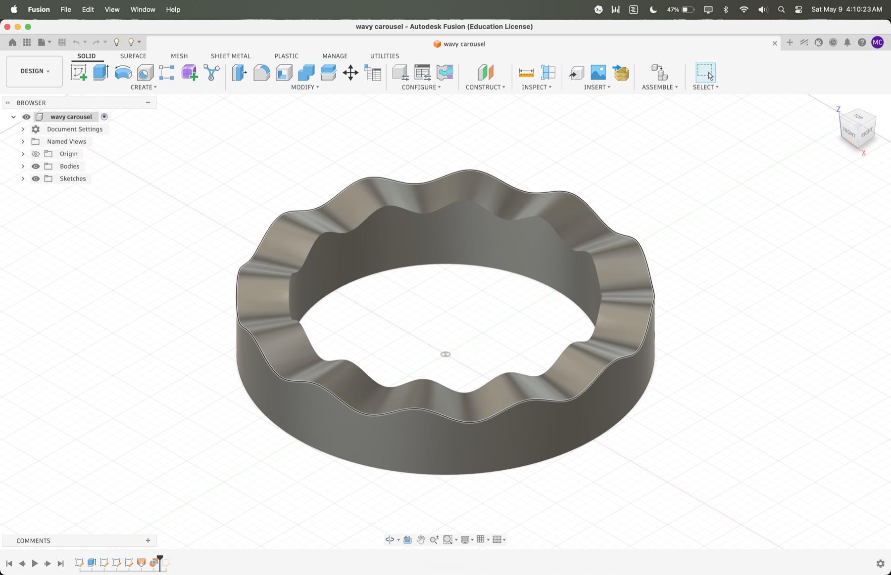
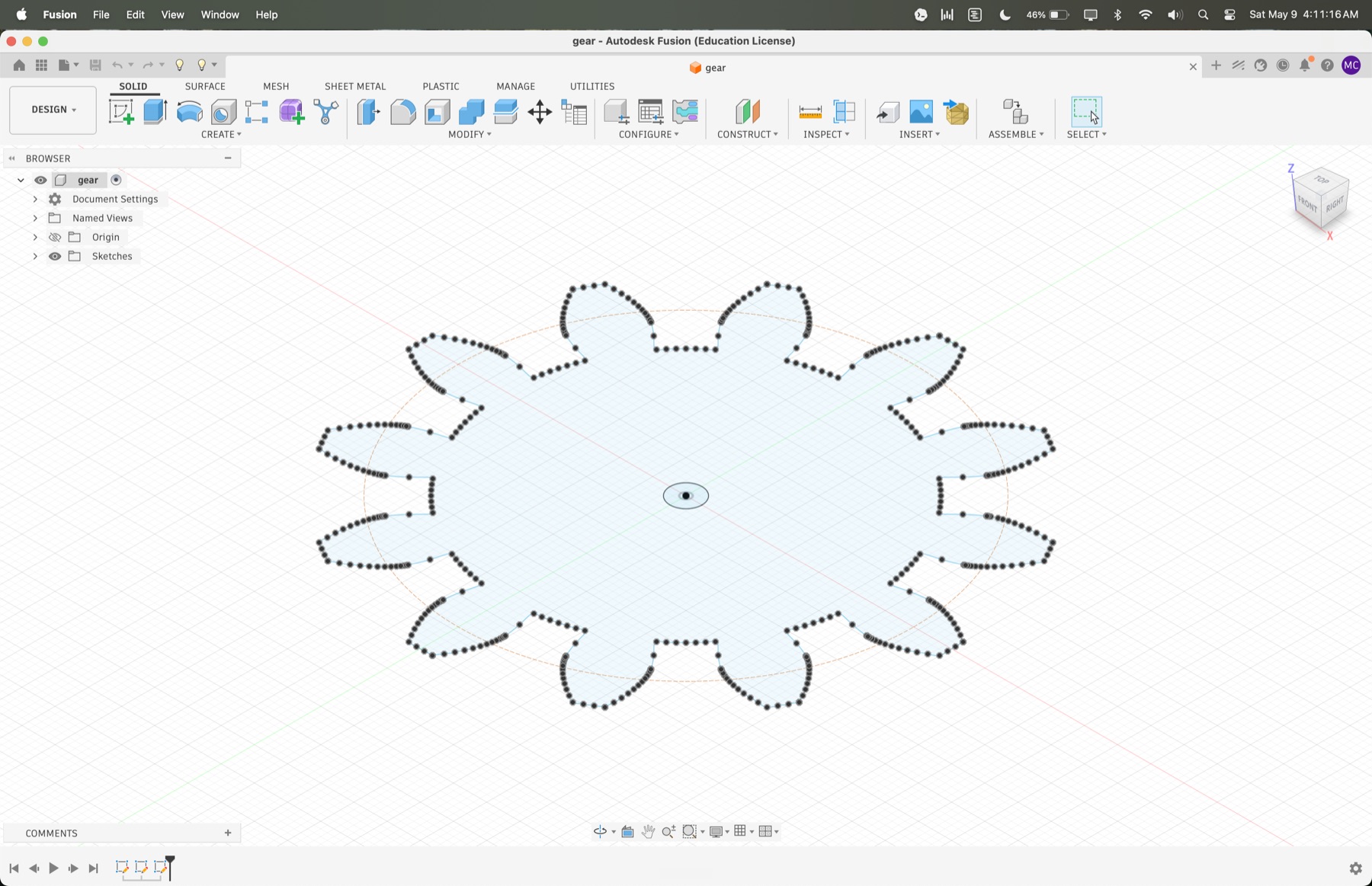
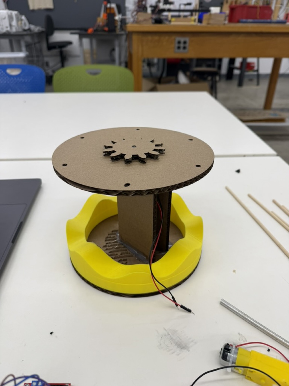
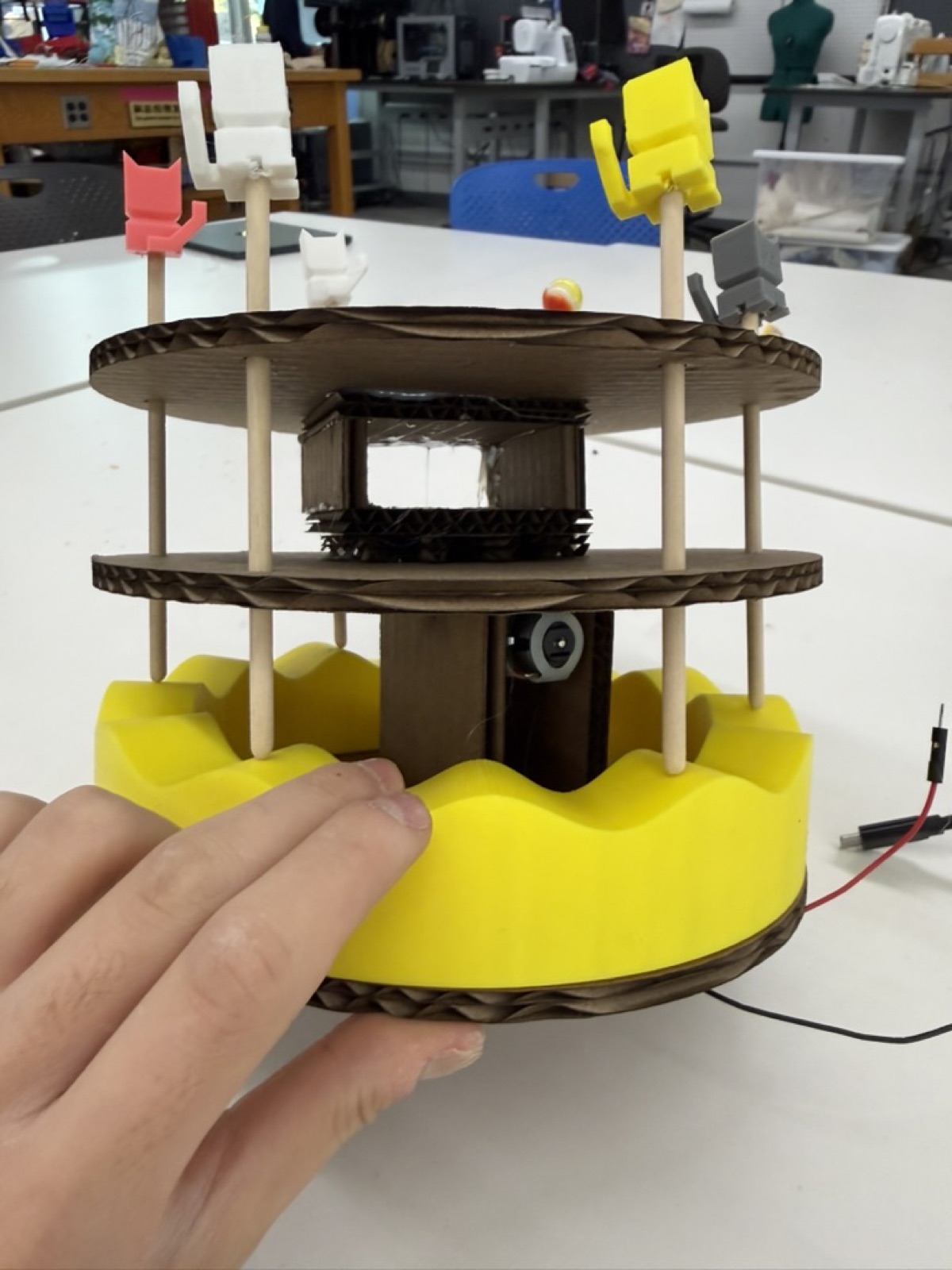
I considered using a cam to drive the up-and-down motion, but cams are really designed for a single motion, and bringing one into a system that was already rotating would have been a headache. Instead, I landed on a simpler idea which was a 3D printed wavy base that the rods would ride on. As the base rotates, the rods would naturally rise and fall along the wave pattern.
Attempt 1: I made the base in Fusion by extruding a ring and using a spline curve to cut waves out of it. I had a problem with this, however, because the surface that I got after extrusion was not flat. The design I initially made had curves along the z-axis that increased friction and prevented the rods from sliding up and down smoothly. In addition, the rods were drifting diagonally instead of moving straight up and down, which broke the whole mechanism.
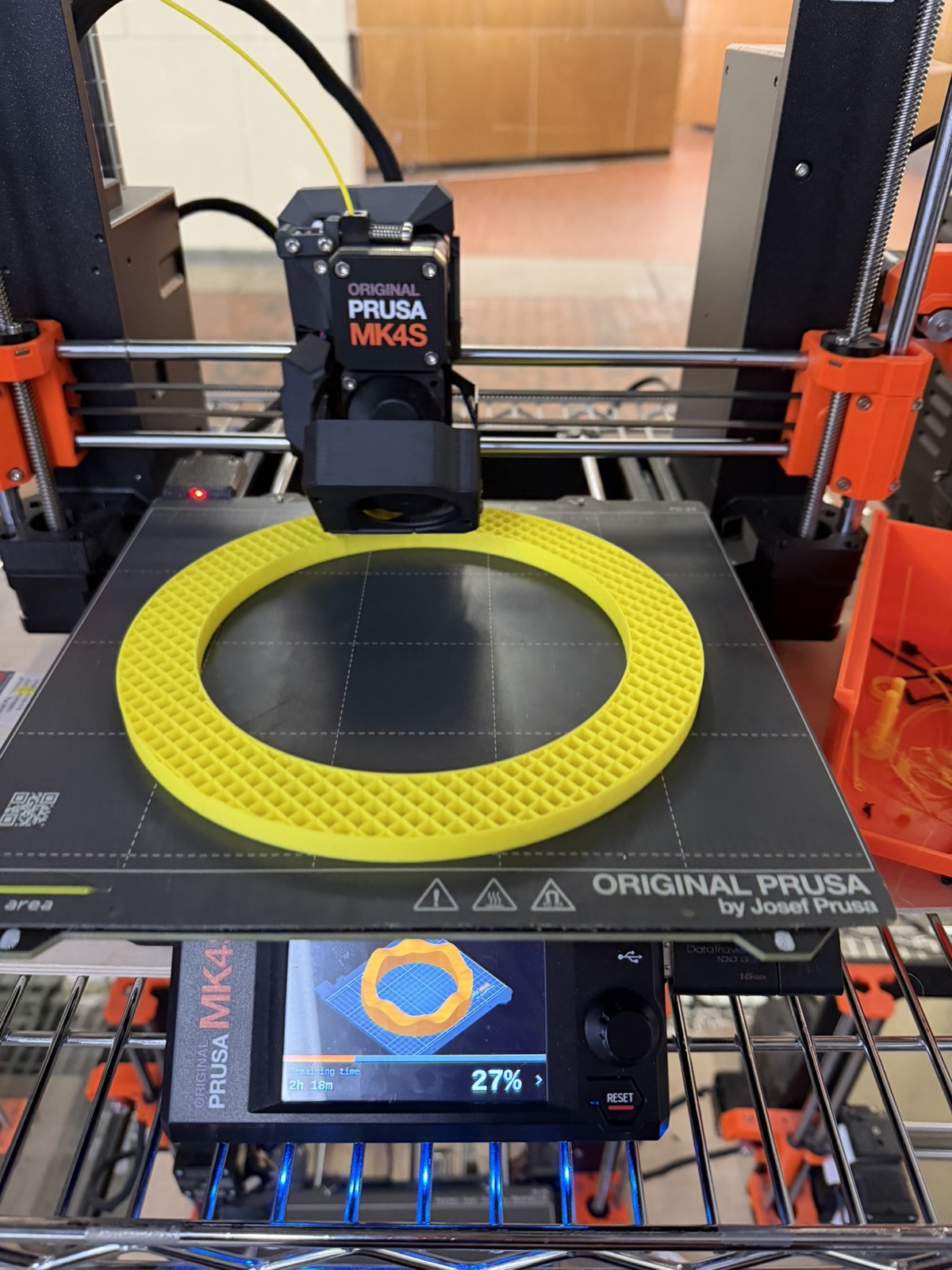
Attempt 2: I went to reprint and ran into my first 3D printer disaster. A glob of yellow PLA formed around the nozzle and ruined the print. I learned the hard way that you really need to stick around and watch the first layer go down before walking away and trusting the printer to do its thing.
Attempts 3-5-ish: I went through about three more iterations dialing in measurements.
Ultimately, I made it work by making two fixes:
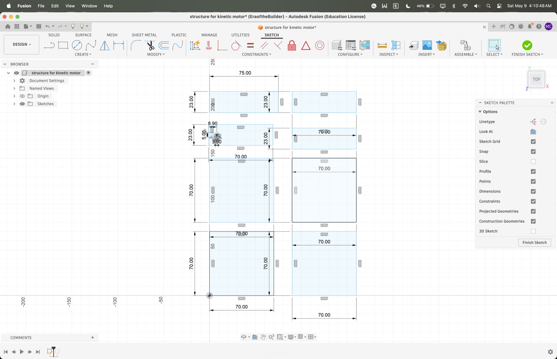
To secure the rods in the vertical position, I laser cut a cardboard piece with holes sized for the rods and stacked it above the base. I had to go through several iterations of designing the cardboard cutouts in 2D in Fusion, including adjusting the diameter of the holes that the rods passed through.
Initially, I chose a smaller hole size because I wanted the cardboard to hold the rods vertically instead of at an angle. This restricted the up-and-down motion of the rods and increased the friction between the wood and the cardboard cutout itself. After about five to six iterations on the cardboard cutouts, I found a design that worked, with a larger hole size of 5 mm for the first top layer and a smaller hole size of 4.8 mm for the second layer that aligned the rods vertically.
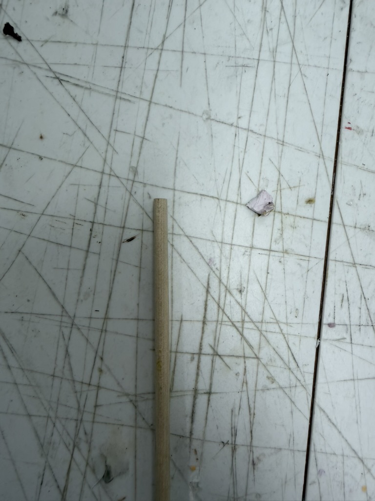
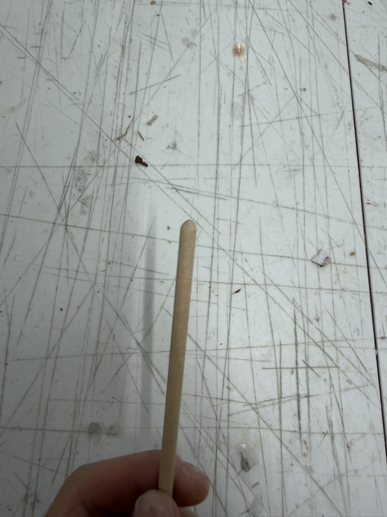
Even with the better base, the wooden rods had way too much friction at their bottom edges where they met the PLA. I needed to round those edges so the rods could ride the waves smoothly.
I considered two options:
I actually tried both, but I had a hard time getting the supports off the press-fit caps cleanly, so I went with sanding. It worked very well. The first time I got a full rotation working on the benchtop DC power supply, I just stood there in awe with Bobby. TBH, I had lost faith in the middle of this project since the motor could not overcome the friction. I thought it was over, so seeing it finally rotate was so nice.
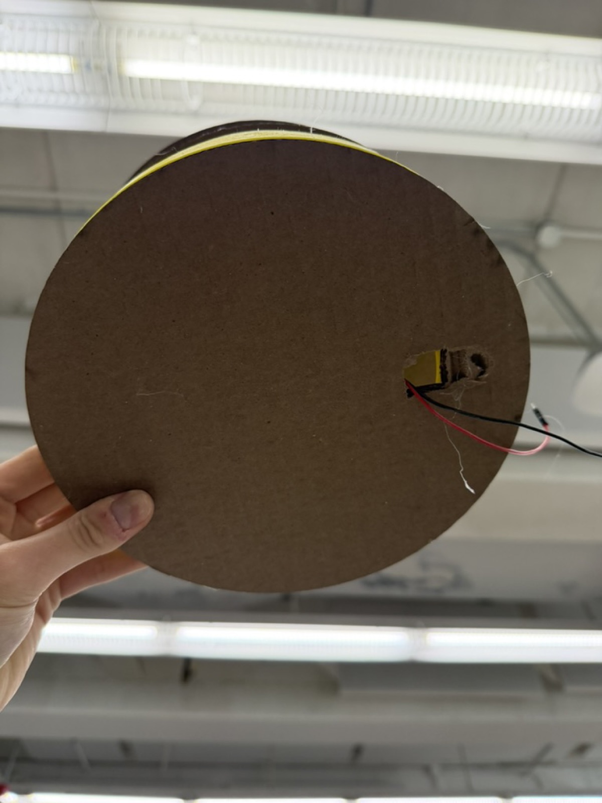
In my final iteration, I also cut a hole at the bottom of the cardboard base to let the motor wires escape. I had not done this in the previous version, and the wooden rods kept crossing paths with the wires as they rotated, which messed with the motion. It made a big difference!
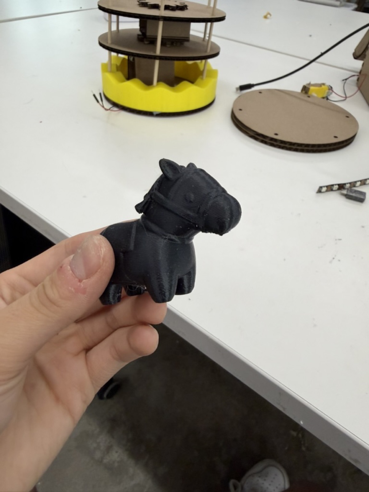
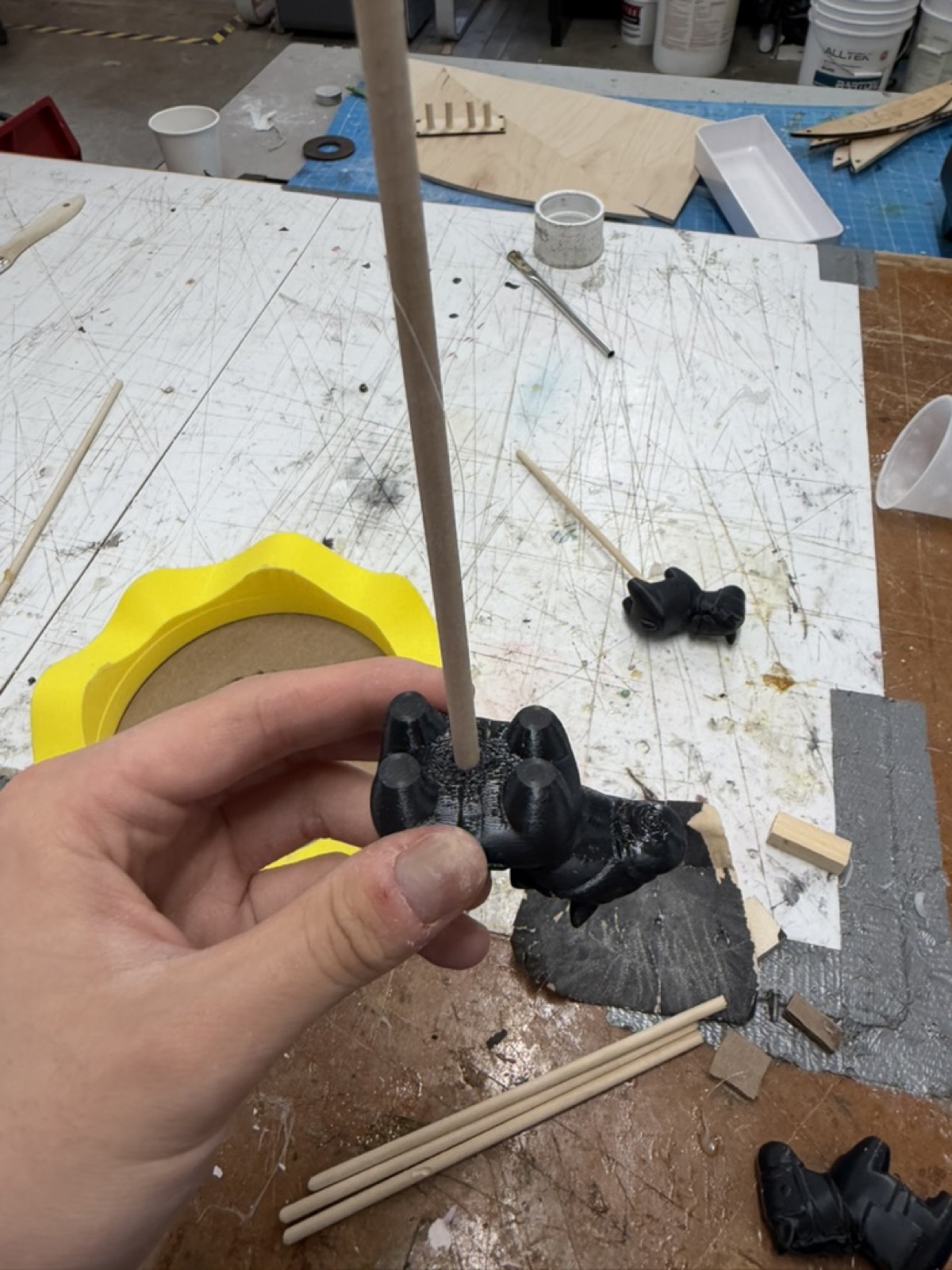
For the actual objects on the merry-go-round, I initially found a design for a cute horse on MakerWorld and printed out a few of them. But once I printed and mounted them, they were way too heavy. The weight that they added increased the friction between the rods and the PLA base and the motor did not work as well.
I realized I needed something lighter. Looking around the PS70 lab, I noticed some calibration cats Jessica had printed previously and left lying around. They were cute, no one was using them, and they were light, so they became my objects for the merry-go-round!
To attach them to the rods, I considered:
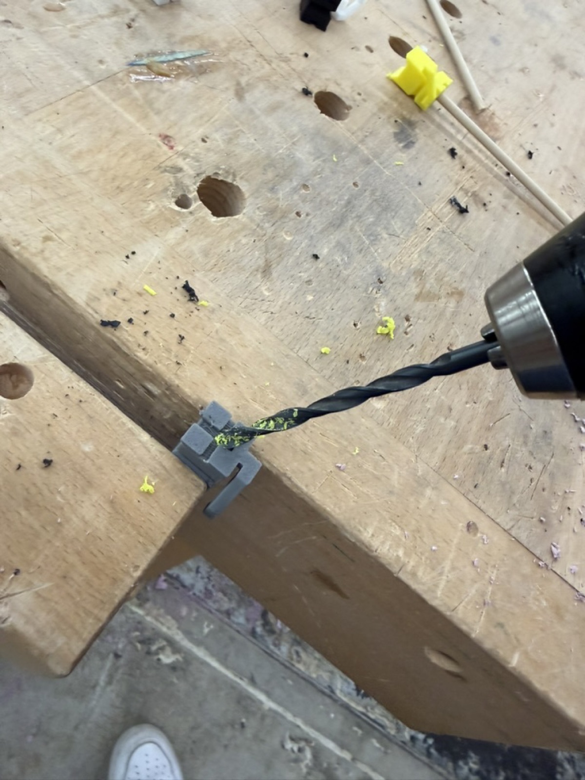
Bobby suggested a third option which was to drill a hole into each cat using a drill bit matching the rod diameter, which was 5 mm. I went with that, and they slid onto the rods perfectly.
This was by far one of the hardest projects I have done so far. Doing two motions at once, rotation and vertical movement, was a much bigger challenge than I expected, and I went through a lot of failed iterations before things clicked. I came out of it with a much better understanding of how DC motors actually work under stress, and I gained confidence in my skills in both 2D and 3D design with the laser cutter and the 3D printer.
It was really cool to finally see this come together. Merry-go-rounds were something I used to beg my parents to ride at the mall as a kid, and now I have built a prototype of one myself in the lab!